With the website finished, I finally had time to continue programming and testing my LibreServo, but the joy was short-lived.
After soldering the three PCBs together, I proceed to power the LibreServo for the first time from a battery instead of the ST-link programmer ... and a white smoke preceded by sparks made an appearance. The STM32F302 microcontroller has been completely blown up, and there is a huge short between ground and the 3.3V line. After looking closely, I see that there are tin chips between the legs of my microcontroller, right between vdd and vss! Is it possible that when welding the three PCBs I was not careful enough and some "chips" has ended up where it should not, or has it been the sparks themselves that have caused it?
I unsolder the microcontroller and re-solder a new one. I check the power lines and there is no short circuit. Let's get to work again! And again white smoke... What's going on?!
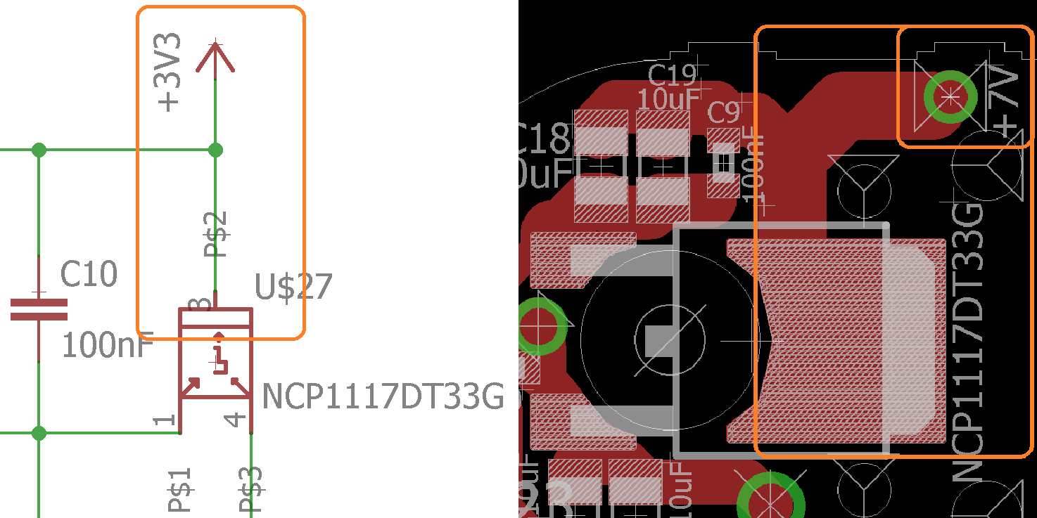
Desperate I disassemble the PCBs, power up the PCBs again with the linear regulator... and I see the catastrophe. Where it should generate 3.3V, there is 6V (with a 7V input from the lipo)... I check my eagle documents and I see the mistake, the schematic does not correspond to the PCB! When I made a special footprint for the linear regulator, at the time of linking that footprint with the scheme I changed the order of the pins and from there everything is history and white smoke.
Design error

Here it is some photos for posterity of LibreServo v1b completely soldered:
LibreServo v1b Gallery
In order to correct this failure it is necessary to change the design of the LibreServo PCB... so since I am going to design new PCBs, I will try to collect everything I learned (from what little I have been able to test) and generate a new design with several fixes on all PCBs, not just this error. LibreServo v1c, here I go!


