Designs

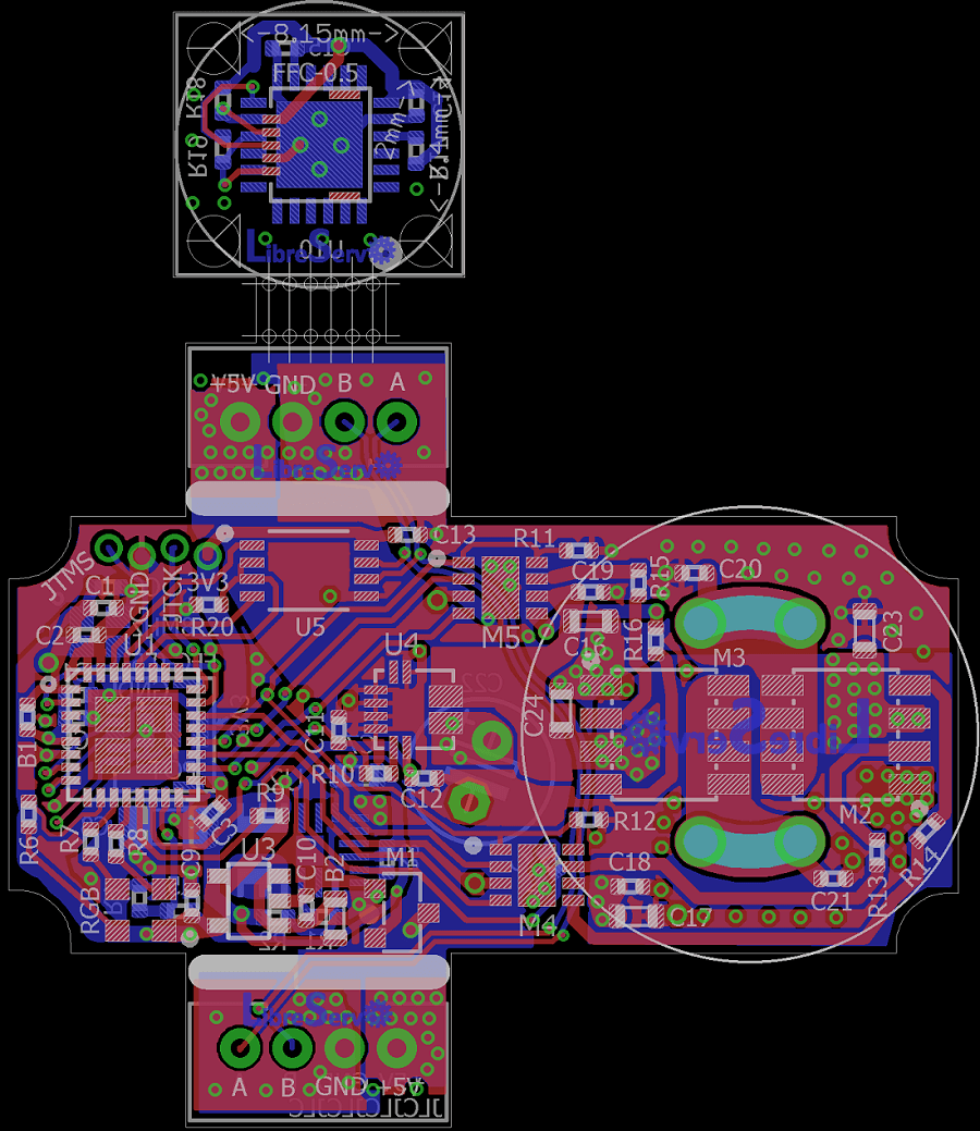
LibreServo v2.3.1. Release Version
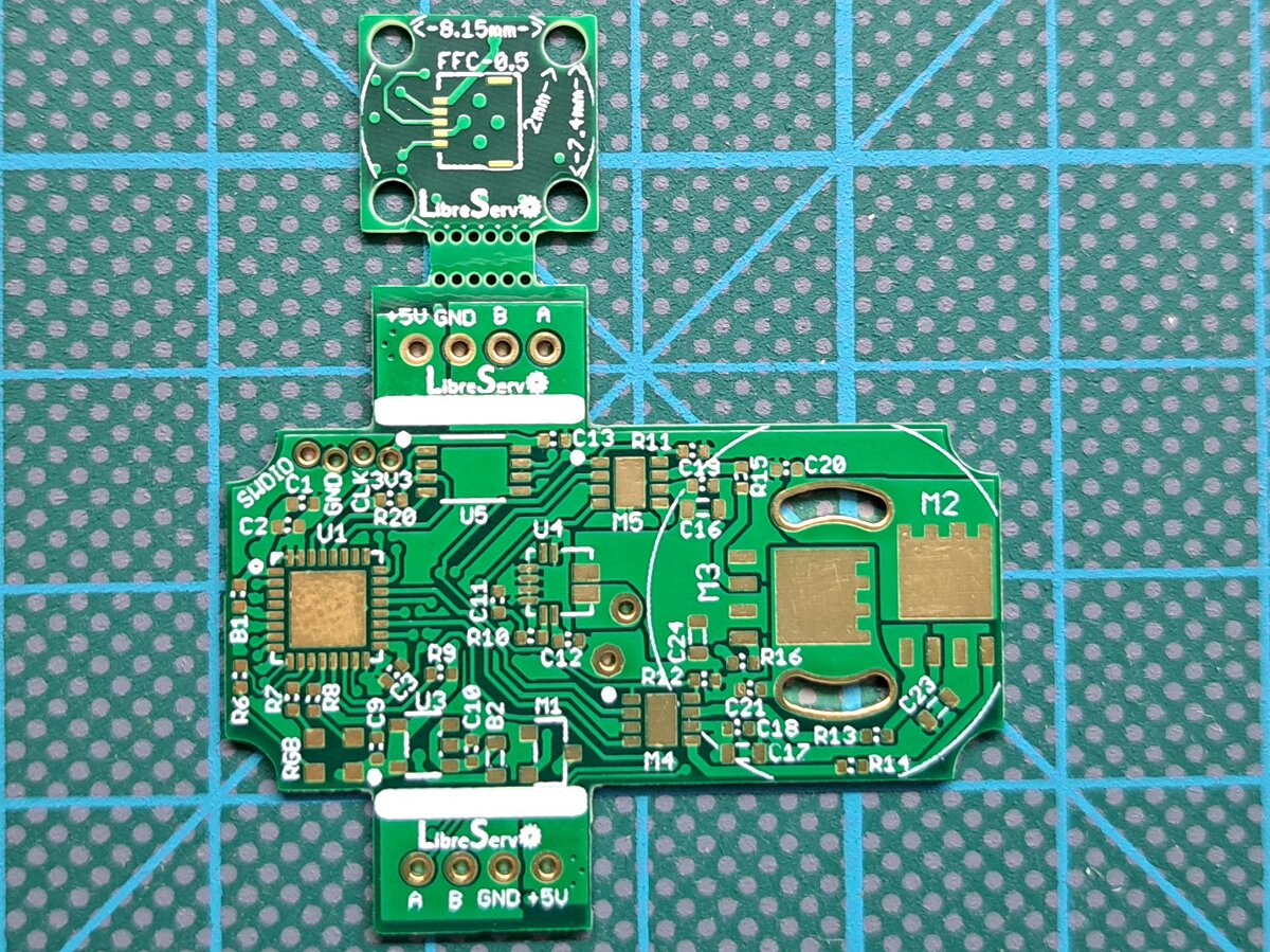
LibreServo v2.3.1 Servo hack LibreServo v2.3.1. Release Version

LibreServo has finally reached the first final Hardware release (version 2.3.1)!

party


It has been a long road and there is still a long road ahead, but now on the software side. LibreServo will not stop here and later on there will come new projects that make use of LibreServo, like a possible 3D biped robot, but all of that will come in the future and all of it will be announced here so let's stop the guessing and talk about the now.

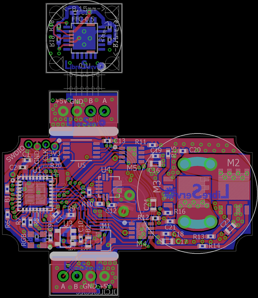
Last minute changes at the time of manufacture the final version of LibreServo

🎉I have already sent to manufacture the final version of LibreServo to JLCPCB!🎉
In total there have been 50 PCB boards (50 because they were the same price as 30) of 0.8mm thick and of the highest possible quality; 6 layers, ENIG finish, epoxy filled and capped vias, PCB material upgraded to FR-4 TG155... Everything came out to me for about $93.24, which with VAT and shipping goes up to $118.18. That gives a base price of about $2.36 per LibreServo. Making the four-layer version of LibreServo, in HASL finish (with lead), FR-4 TG135-140 material and tracks simply covered with solder mask comes out to $56.20, which with VAT and shipping goes up to $75 for a total of $1.5 each LibreServo. Personally I think that making it in 6 layers and the rest of the improvements are well worth 0.86$ per board, but it is something that each one will have to value and that certainly LibreServo is going to work equally well in both configurations.

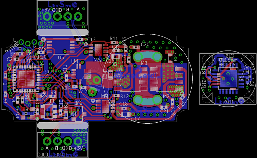
LibreServo v2.3 schematics. Candidate version

LibreServo v2.3 PCB servo hack LibreServo v2.3 PCB

A few days ago I presented LibreServo version 2.2 and announced that I had one last final change... this time the wait has not been long and I bring the new version of LibreServo, version 2.3.
This version should already be the final hardware version of LibreServo .
The biggest change that LibreServo has had in this latest version with respect to the previous one is the H-bridge. Risky move seeing what it cost me to make it work but I think it will be a remarkable improvement and the missing component to make LibreServo the definitive option.

LibreServo v2.2. Pre-Release version?

LibreServo v2.2 PCB servo hack LibreServo v2.2 PCB

Pre-final version. This was going to be the final version, was going to be, because in the end it is not going to be.

  • The oscillator has been changed for a more compact one.
  • The position of several components has been slightly reworked
  • Ground planes have been generated on the outer layers
  • The position of the silk-screen printing has been repositioned with the idea that the vias will be capped and it will be possible to silkscreen on top of them
  • The PCB has been narrowed by a few tenths of a millimeter to fit perfectly to the servomotors
  • The two PCBs have been joined by using mouse-bites

In general, they are all small changes, but... just before placing the order I went back to review each and every one of the components, and there is one that I have decided to change and it is a very important one that has been in LibreServo from the beginning. In the next article I will unveil the final change 😉

LibreServo v2.1 Schematics

LibreServo v2.1 PCB LibreServo v2.1 PCB
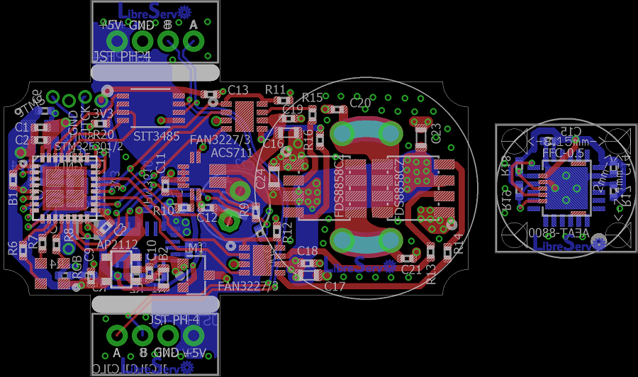
These schematics will not last long because new changes have already been made and will be sent to manufacture in the coming days if all goes well. The order of the next version will coincide with the Chinese vacations, but I hope not to have any problem except some small delay already announced by the manufacturer JLCPCB.

In this LibreServo version, the main PCB, goes from 4 to 6 layers because JLCPCB, as we mentioned in the article of changes in LibreServo v2.1, has made a very aggressive offer in which it is cheaper to manufacture a 6-layer PCB instead of 4, taking into account that in 6 layers you get for free the ENIG finish (in gold) and the vias are filled and covered, in other words, a totally professional finish. It is a really crazy offer.

Despite all this, of course LibreServo will maintain full compatibility with 4 layers and only when generating the gerbers the central layers are removed and the matter is solved.

LibreServo v2 Schematics

PCB para test LibreServo LibreServo v2 PCB

I had pending for months to upload the schematics to the web. The schematics are exactly the same with which I made the LibreServo v2 PCBs but with the texts corrected in position so they read better.

In previous posts as you can read in the article of the first LibreServo test board and in the conclusions of the second LibreServo test-board, the LibreServo changes were massive in each and every aspect. Virtually every component was overhauled and moved to a two PCB, four-layer design.

We have a winner. Test results in PCB test 2


LibreServo sending data via RS485 to Arduino plotter

After several tests, the LibreServo hardware is finally chosen and it's working, even the H-bridge that gave me a lot of problems! In general, all the parts of LibreServo remain as they were, because they were already working correctly, except the parts are discussed in this article.

New PCB Test v2 for LibreServo


Hello World in LibreServo PCB test v2

A month ago I was analyzing the results and conclusions obtained with the LibreServo test PCB v1 and trying not to lose momentum this month I have designed, I have ordered new PCBs and I have already assembled the LibreServo test PCB v2! 🥳

It is the first PCB that I have designed with 4 layers for LibreServo and I hope that this will mitigates some issues with the H-bridge that I think comes, in part, from electronic noise. For the rest, it is a PCB with the final components, it is closer to the final design in which I have forced myself to put the components as close as possible to each other to see the real limit between what is designed and what can be easily welded without overcomplicating things, everything holds up on paper but then you have to bring it to reality.

Results and conclusions of the tests

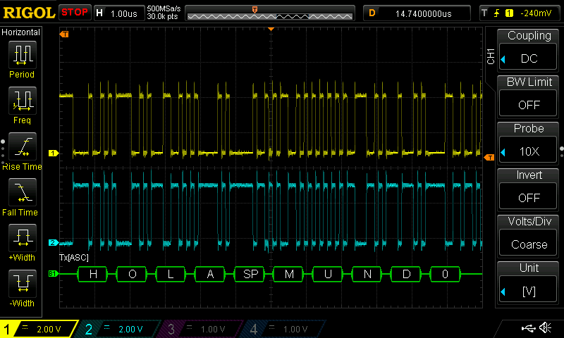
RS-485 9 Mbps Hello World
RS485 Hello World at 9 Mbps

After analyzing all the parts of LibreServo, I have decided to make several design changes again. I am happy with the results obtained with the test board since without it, it would have been impossible to analyze all the components separately and detect all the errors and faults that I have found, it is something that I should have done from the beginning and it would have saved me a lot of time. The topics to be discussed are:

  • Current Sensor
  • Protection against change of power polarity
  • New power supply, mpm3610 + ap2112
  • NTC temperature sensor
  • New more compact RGB led
  • RS-232 vs RS-485 serial communication
  • New AEAT-8800 magnetic sensor
  • H bridge
  • Next PCB (4 layers)

Power Analysis (MPM3610 + Ferrite + AP2112)

MPM3610 and AP2112 circuit with Ferrite MPM3610 and AP2112 circuit

One of the parts that I have changed the most in LibreServo and thought about is the power supplies. In previous versions it was a linear regulator that I reduced in size, but the truth is that I was not at all comfortable since if LibreServo was powered with only 12V, the linear regulator should dissipate up to 1.74 Watts and in 16v 2.54 Watts... something that was really unreal that it could handled.

A few months ago I discovered the MPM3610, and this finally made it possible for me to design the power supply as I wanted. This tiny component is a powerful 1.2A step-down that supports up to 21V input and also has a built-in diode and coil! It is the latter that makes it perfect for my design, due to the reduced space used, being the only step-down that is manufactured that has an integrated coil and diode in the same package. The difference between using a step-down and a linear regulator is that a linear regulator from 3.3V to 12V gives an efficiency of 35%, while a step-down of 80% or higher, the rest is dissipated in heat, so one is much more prone to overheating than the other. The downside of using a step-down is that they are quite noisy and their output is not as clean as one from a linear regulator.